Modelling blocks for Space Engineers is a process that
involves a lot of intermediary files and manual parametrization.
This add-on simplifies the steps you need to take to get from a 3D mesh in Blender to
Space Engineer’s own .mwm mesh-format. To do that
-
The add-on provides property panels for all the special data SE stores inside an
.mwmfile directly in Blender. -
You use Blender layers to define the main model, the collision model, mount-points, mirroring-settings, level-of-detail models and construction stages.
-
The workflow that configures and runs the conversion-tools (Havok, MwmBuilder) for you is customizable to suite your needs.
| The add-on (and this documentation) expect you to know how to work with Blender. So if you are new to 3D modelling you should probably learn how to do that first before you continue. |
Installation
Getting the tools
To get started first you need to download and install all the required tools.
- Blender
-
Get version 2.75 or later (100MB), 2.77 is current at the time of this writing.
- The Havok "Content Tools for Game Artists and Designers"
| The free offering of these tools has been discontinued. Currently there’s no alternative available. Please also take a look at this forum thread to see if the situation has changed. |
Havok provides the filter manager hctStandAloneFilterManager.exe that’s used to create rigid-body physics data.
The default install location is C:\Program Files\Havok\HavokContentTools
| Space Engineers now also seems to support Havok 2014. The addon will probably also work with that version but this hasn’t been tested. |
- The Havok FBX Importer
-
This is a separate download (3,5MB) because I had to fix a view things in the sources and compile it against Havok 2013.1 (the official download is compiled against Havok 2014). The .zip contains just one executable file. It’s probably a good idea to put it into the Havok Tools directory.
- MwmBuilder
-
This one comes with the Space Engineers ModSDK and is located under
Tools\VRageEditor\Plugins\ModelBuilder.
If you try to export and MwmBuilder fails with the error message
"Error loading unmanaged library from path: Assimp32.dll"
this is a strong indication that you are missing a software library on your system.
You can download that from Microsoft.
Get the VSU_4\vcredist_x86.exe package.
|
Currently (version 1.134 - 1.146, and possibly later) MwmBuilder is unusable.
It fails with a System.BadImageFormatException.
You need to use an older version.
|
Installing the Add-on
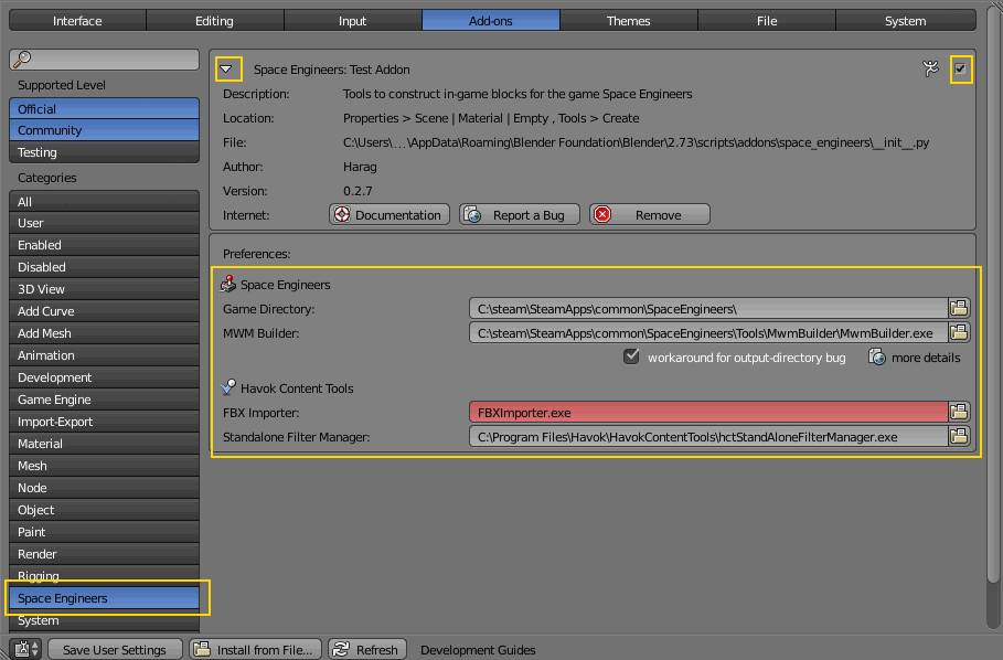
Once you got the current version (50kb) install it in Blender like any other third-party addon by going to the user preferences, switch to the "Add-Ons" tab, click on "Install from File…" and point Blender to the downloaded .zip.
Like any add-on you need to enable it after you’ve installed it. You can find the add-on by using the search box or going to the Category "Space Engineers". After you’ve enabled the add-on open its settings by clicking the arrow on the left. You need to provide all the paths in the list.
| Don’t forget to "Save User Settings". |
Using the Add-on
File layout
The add-on only has one mandatory requirement in regards to the folder layout:
| The .blend file(s) must be in the base-folder of your mod. |
This is necessary so that all relative paths (textures, models, etc.) are calculated correctly.
Scene Layout
The addon only provides its tools to scenes that are marked as containing a block.
You do that on the Space Engineers Block panel of the Scene properties-tab.
Here you also find the settings that are relevant for the basic layout of the block:
-
Is the block a large or a small block?
-
Should the export automatically create a small version of your block if it is a large one?
-
What is the dimension of you block in in-game grid-units?
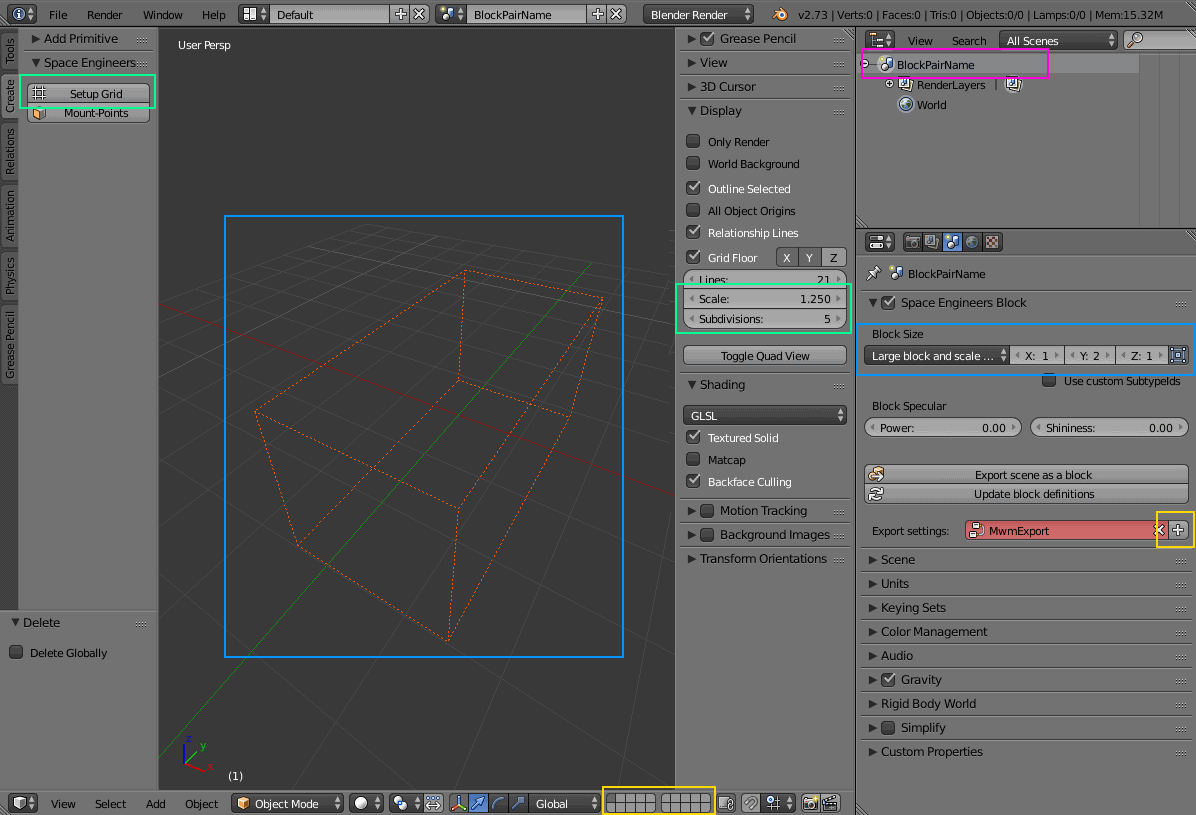
The layers of the scene contain the different components of a block. Below is the default layer-setup that is described in the following sections.
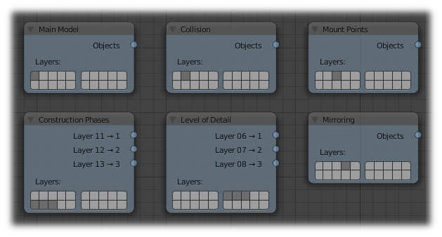
Main Model
The first layer contains the model of the fully-built block. You don’t need to restrict yourself to only one mesh-object on this layer. If it’s useful to split your block into several objects — probably to apply modifiers to some of them — by all means do so.
Collision Model
The second layer contains the simplified meshes that represent the block’s collision shape. If you don’t provide any collision meshes the resulting .mwm file will not contain collision data and SE will default to a simple collision box that encompasses the volume of the whole block.
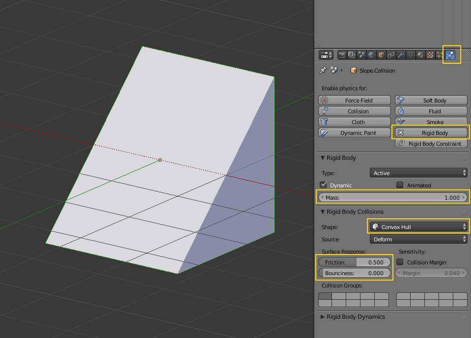
Havok, the physics engine of SE, requires some settings to do its work.
You provide those on Blender’s Physics tab by enabling Rigid Bodies for your collision meshes.
Only the settings Shape, Mass, Friction and Bounciness (Restitution) are exported to Havok.
Of those settings Shape is the most important because it has a significant performance impact.
Whenever possible try to only approximate the shape of your block.
Use primitive shapes like Box or Cylinder. Use Convex Hull only if necessary. Avoid Mesh collisions.
| Make sure you apply object transformations to all collision objects before export. As a rule of thumb the add-on never modifies your objects on its own so you have to do this yourself. If you don’t the collision shapes will most probably be rotated or positioned wrong. |
Blender offers a Cone primitive shape but Havok has no support for that.
If you use a Cone shape it will be silently treated as a Convex Hull on export.
|
Mount Points
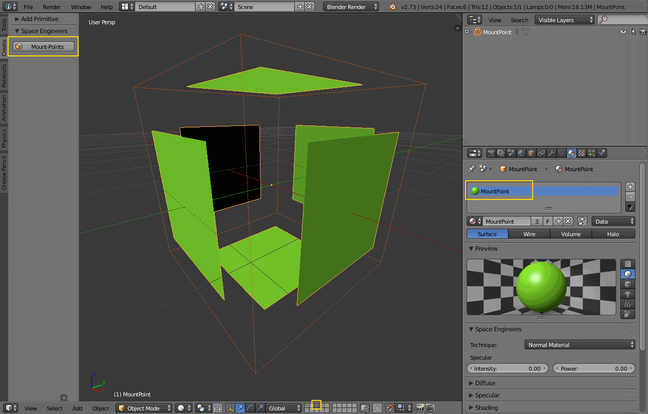
The third layer defines the mount points of your block. The meshes on this layer are not directly exported but are used instead to calculate the mount point definitions .
This works by creating rectangular faces that use the material MountPoint and are aligned to one of
six sides of the block. To quickly create the material and an object that has one mount point face for each
of the six sides use the corresponding button on the Tools panel of the 3D view.
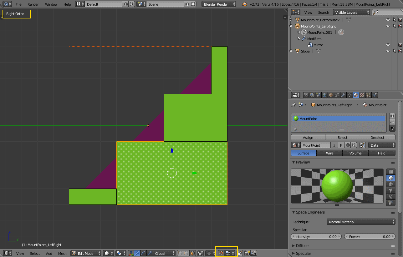
Duplicate, resize and move those faces in edit mode to create more mount points for a side of the block.
You can also split out faces to several objects if you want to apply
modifiers like 'mirror' or 'array'
to some of the mount point faces.
For mount point editing it is a good idea to switch to ortho-view (Numpad 5) and
turn on 'snap to grid'.
You can also tell the add-on to show the block’s bounding box by enabling the option on the
scene tab .
It’s dashed, orange lines represent the space your block occupies in-game.
This should help you to position the mount points correctly.
If you don’t provide mount points none will be calculated. The game defaults to full mount points on all sides of the block in that case.
Construction Stages
Layers 11-13 are used for the construction stages of the block. There is one layer for each stage of construction, from earliest to latest. If you change the number of construction layers you increase or decrease the number of construction stages. A block is allowed to have no construction stages at all.
| If you don’t have meshes on a construction layer it will be skipped and your block will have one stage less. |
By default the construction stages reuse the same collision shape your main block model uses. It’s possible to change that using different export settings. But keep in mind that can be dangerous to a ship or the player if a block changes its physical dimensions when it is welded to completion.
| A Blender mesh-object can be assigned to several layers. So if your construction models get more and more detailed you can start with the basic shape as one object that is visible on all construction layers and then progressively add more objects towards the final construction layer. |
Levels of Detail
Layers 6-8 are used to model versions of your main model that have progressively less detail. The game can display those models when the block is too far away to see the small details of your main model. This way less triangles need to be rendered which is good for performance. The default distances at which the models are switched are 10, 30 and 50.
| If you don’t have meshes on a LOD layer it will not be included in the export and the game will not switch models at that distance. |
DirectX 9 Textures
This is a small excursion into how SE textures a block. In DirectX 9 rendering mode the game uses two textures per face of a mesh. Both of them have four channels (RGBA).
| As of 2016-03-31 the DirectX 9 renderer is only used in the legacy version of Space Engineers. So you only need textures for it if you intend to release a mod that still runs with that version. You can skip ahead to DirectX 11 textures if you don’t. |
Diffuse/Emissive
The internal name of this texture is DiffuseTexture.
By convention Keen names texture-files of this kind with a suffix of _de.dds.
The RGB-channels of this texture represent the diffuse color of a face—just like with any regular digital image.
The A-channel of the texture does not represent the transparency of the pixels, though. Instead it tells SE how much emissive light a pixel gives off in the dark. Strangely a value of 0 means full brightness, a value of 255 means no emissivity. In theory the light given off could be different from the diffuse color of the pixel but in SE it is always the same as the diffuse color so there are no extra channels for that.
Recolorable Blocks
If instead the texture-filename ends in _me.dds the A-channel serves a double purpose.
Here the values in the range 115 to 140 represent a mask that controls
which parts of the texture can be recolored by the player.
-
A value of 115 means that the pixel is fully recolored with the player-chosen color.
-
A value of 140 means that the pixel keeps its original color.
-
A value in-between mixes the colors with the corresponding ratio.
Recoloring uses a HSV color-model in which the player-chosen hue replaces the original hue. Saturation and value are added and clamped at a maximum of 100.
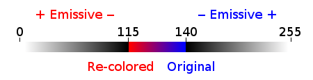
If the value of the texture’s A-channel is not in the range 115 to 140 it still controls emissivity but the values have a slightly different meaning.
-
A value of 0 still means the pixel is fully emissive. It also means it is fully recolored.
-
A value of 115 means the pixel has no emissivity. Again, it is fully recolored.
-
A value of 255 also means the pixel is fully emissive. But here the pixel is not recolored.
-
And finally a value of 140 means the pixel is neither emissive nor is it recolored.
Normal/Specular
Internally named NormalTexture this kind of texture has a suffix of _ns.dds and contains no color information at all.
The RGB-channels contain a standard DirectX normal-map.
The A-channel tells the game how much of a material’s maximum specularity settings it should apply to a pixel.
A value of 0 means "don’t apply any specularity", a value of 255 means "apply full specularity".
| The A-channel normally controls transparency in tools like Gimp or Photoshop so it can be hard to edit SE’s textures. It’s therefor a good idea to separate the channels in those tools. For example, in Gimp you can convert the A-channel into a layer mask and edit and view that separately. |
DirectX 11 Textures
In DirectX 11 mode SE employs Physically Based Rendering (PBR) to render 3D objects. In this mode it uses another set of three or four textures.
PBR textures
The ColorMetalTexture (_cm) and NormalGlossTexture (_ng) correspond with the common
metal/roughness workflow
where glossiness is just the inverse of roughness. Here the normal map uses the OpenGL convention,
i.e. in comparison to the DirectX convention the green channel is inverted.
AO, Emissivity and Recoloring
The AddMapsTexture (_add) combines additional greyscale maps in its four channels:
-
The R-channel contains a baked Ambient Occlusion (AO) map where a value of 255 means 'no occlusion' and 0 means 'fully occluded'.
-
The G-channel contains the emissivity. 255 is fully emissive, 0 is non-emissive.
-
The B-channel is currently unused and should always be 0.
-
The A-channel contains the re-coloring mask. The difference with the DirectX 9 equivalent is that the parts of the ColorMetalTexture that are selected by this mask are usually colorless.
Transparency
The AlphamaskTexture (_alphamask) is optionally used to make parts of a texture transparent.
It has a single greyscale channel which really only differentiates between two states:
fully transparent below a value of 128 or fully opaque at 128 or above.
This is most useful for things like foliage and small details like facial hair.
If you want to use this texture you need to also set the technique of the material that uses it to Alphamask.
Materials
Texturing
Materials are what you use to tell SE which texture-files to use for the faces of your meshes (and you use UV-mapping to tell the game which part of a texture to use for a face).
In Blender there are several types of materials depending on the renderer you have chosen. If you choose Blender Render as the renderer you can switch between simple and node-based materials. If you choose Cycles as the renderer you can only use node-based materials.
This add-on needs you to use node-based materials because it sets up several nodes to preview the textures in Blender.
It also requires the use of Cycles because the nodes it sets up are meant for this renderer.
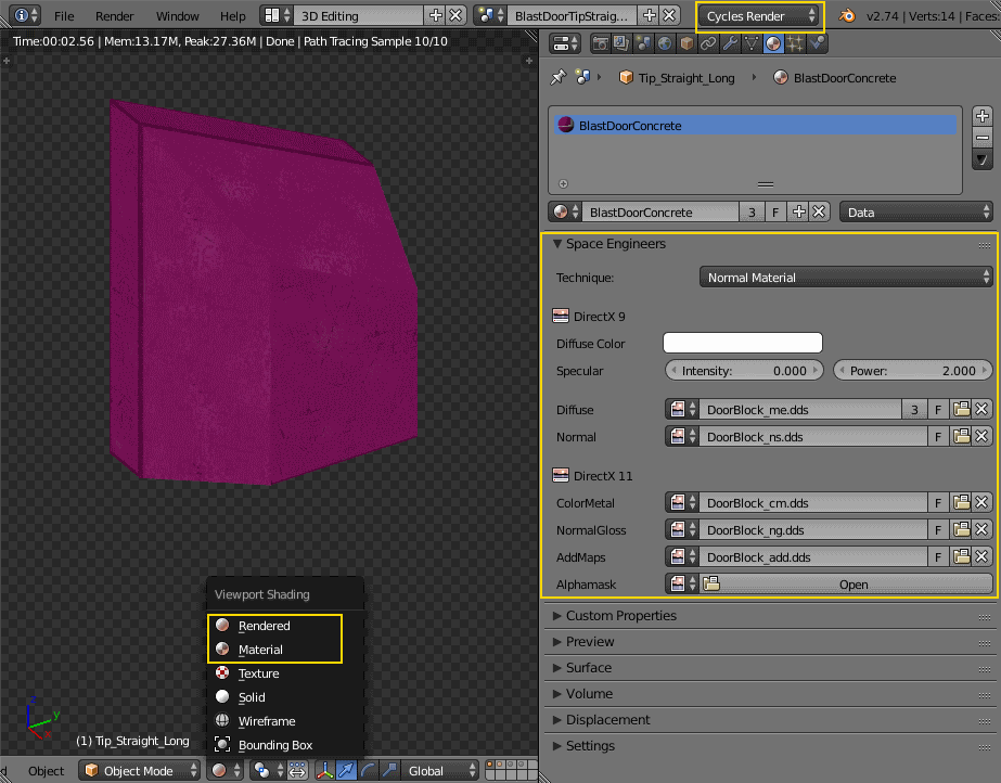
So to set a material up for use with SE first switch the scene to use Cycles Render
and then use the  button
on the Material property tab. You need to repeat that for each new material you define.
button
on the Material property tab. You need to repeat that for each new material you define.
By doing that you get six texture-slots for the different kinds of textures SE expects. Point them each to the texture-file corresponding with its name.
| You won’t be able to see any textures on your meshes until you set your viewport-shading to Material. Setting it to Rendered looks even better but requires a lamp in the scene or everything will be black. |
In a previous version of the add-on the Blender Render and its texture-slots were used.
This setup still works but only for DirectX 9 textures. If your .blend still uses it there is an operator
Upgrade All Materials to use Nodes you can use to get to the new material setup.
It’s not available on any panel, you need to use Blender’s quicksearch (Space) to access it.
|
Texture Paths
The game resolves texture-paths relative to two different base folders.
The first is the game’s Content/ folder (so you are able to reuse the game’s textures),
the second is the root-folder of the mod. This is why the add-on expects the .blend file to be in the root-folder
because it then automatically knows the location of that folder without you telling it.
When exporting .mwm files the add-on derives the correct relative texture-paths by comparing each texture’s absolute path against the root-folder of your mod and additionally to the game’s location (as configured in the add-on preferences).
Don’t use texture-files that are not inside the mod folder or the game’s Content\ folder.
Neither Blender nor the add-on will prevent you from doing so but this will not work when exporting .mwm files.
|
| The add-on does not check if the path of a texture actually points to an existing file. But it’s easy to spot missing texture-files when you configure the 3D view to display meshes with their materials. |
Specularity
Specularity is a DirectX 9 mode-only setting and is configured per material. You do that in the "Space Engineers" panel of the material. The values you set there are the maximum values for that material. How much of those maximum values are actually applied to a pixel of a face is determined by the A-channel of the normal/specular texture.
The effect of the two values Intensity and Power are hard to describe so it is best if you play with them
and watch the results in-game. Just know that at high values (30.0 / 30.0) the game’s specularity shader
also starts to mirror the environment like smooth metal would do.
Glass Materials
Glass materials are handled specially by the game.
They have some extra settings that are not contained in an .mwm file
but are instead stored in a file called TransparentMaterials.sbc.
It makes no sense for this add-on to support editing the content of this file
because the settings cannot be viewed in Blender, anyway.
What you get if you change a material from Normal to Glass are the settings that are stored in the
.mwm file on export. For the meaning of these settings please refer to Keen’s
tutorial
on transparent materials.
Special Material Names
Normally you are free to choose the name of a material. But there are some visuals in SE that are only enabled if the material of the face has a special name
Status lights
A lot of block types have some type of status indicator. Landing Gear displays the lock state, several other blocks show if they are powered, conveyors show if the conveyor-line is established or broken, etc.
Because all these are some form of lights Keen chose to use the material name Emissive for this.
If a block has more than one status the materials are additionally numbered, starting with zero
(so Emissive0 through Emissive3 for batteries, for example).
| For status-lights you have basically no control over the color of the face. The game uses hard-coded values to override the color with the typical black, yellow, red, green or blue. |
| It’s easy to spell "Emissive" wrong. If status lights don’t work the first thing you should check is if you named the material "Emmisive". |
Empties
Location Markers
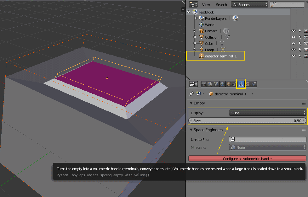
SE uses empties to represent predefined points of interest on a model like terminal keypads, cargo ports or
the location of the thruster flame. The purpose of each empty is determined by its name — i.e. detector_terminal_1
or detector_conveyor_1 for example.
Volumetric Handles
Some empties only serve as location markers. Some others like the aforementioned detector_terminal_1
have some volume to them and you need to point your crosshair inside the volume to interact with the empty in the game.
The size of that volume is determined by the scaling of the empty.
The add-on needs to know if an empty is a volumetric handle because it needs to scale it down in size if the option is used to create a small block version from a large block. To turn an empty into a volumetric handle use the corresponding button This will display the empty as a box with the exact size it will have in-game.
Linking Model Files
Some blocks like doors, rotors, pistons and turrets are composed of several models each of which is in a separate file.
To link from one of those models to the next SE expects empties that have a name starting with subpart_.
For those empties there is the file property on the Data tab of the empty that names the next subpart-file.
Mirroring
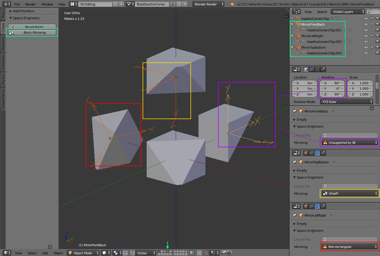
When SE "mirrors" a block on a mirroring-plane what really happens is that a copy of the block is placed on the opposite side of the plane at the same distance to the plane as the original block. Then the copied block is rotated according to the mirroring-settings for the local block-axis that is currently pointing towards the mirroring-plane. So there is a maximum of three independent mirroring-rotations per block.
You can model these rotations in Blender by adding and rotating three specially named empties to the scene.
Fittingly their names are MirrorLeftRight, MirrorTopBottom and MirrorFrontBack.
They need to be placed on the layer that is designated as the mirroring layer in the export settings.
By default this is the fourth layer. Use the corresponding button on the Tools panel of the 3D view to quickly do so.
It’s okay if Blender adds a .001 suffix to the names, the add-on can handle that.
The rotations you set on the empties are only valid for export if they are multiples of 90° — so it’s a good idea to turn on snapping when you rotate them in the 3D view.
Even if you adhere to that rule some combinations cannot be used because SE does not support them.
To check if a rotation is valid watch the Mirroring property on the Data tab of the empty.
| The objects that are attached to the empties are linked duplicates of your main model. So modifying them will also change your main model and vice versa. |
Exporting
Naming Conventions
All names that are used during export are derived from the scene name:
BlockPairName |
|
|
SubtypeId |
|
|
ModelsDir |
the chosen export-path from the scene properties |
|
Model |
|
|
Construction Model |
|
|
Level-of-Detail Model |
|
|
Icon |
|
| The BlockPairName and the SubtypeId are globally visible to all parts of the game. So it’s important that you choose a sufficiently unique name for the scene to avoid naming-collisions with other mods. It’s probably also a good idea to not use spaces in your names. |
You can customize the SubtypeIds of blocks by enabling the corresponding option in the scene properties. This is primarily meant for mod authors that want to use the add-on but need their existing blocks to keep their ids to remain backwards-compatible. Otherwise there is hardly a good reason to change them.
Configuring the Export
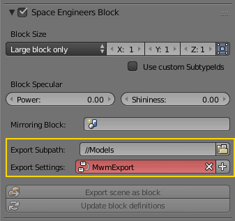
The addon needs to know which folder models should be exported into.
You can configure this per scene via the Export Subpath property in the scene properties.
How the meshes of your scene are exported is configured via a custom Blender node-tree.
Initially your .blend file contains no such node-tree and your scene’s default settings-name MwmExport
will be displayed as invalid. You can create the default settings by clicking on the + next to the settings-selector.
Clicking "Export scene as block" will then immediately export the scene to the chosen folder.
Holding down Alt while clicking the button will export all the scenes in your .blend file.
In this case each scene will use its own folder and settings.
| The chosen export folder needs to be a subpath of the folder containing your .blend file. Otherwise references to your models will be calculated wrong (CubeBlocks.sbc, LODs). |
Exporting .mwm files
By default the export runs through theses steps:
-
Export the collision-meshes to a
.hkt.fbxfile -
Convert the
.hkt.fbxfile into a.hktfile via Havok’s FBX-importer -
Run the
.hktfile through Havok’s filter-manager to calculate and add rigid body data to it -
Repeat the following steps for the main layer and all construction and level-of-detail layers
-
Export the meshes to a
.fbxfile -
Export the info for materials and linked levels-of-detail to a
.xmlfile with parameters for MwmBuilder -
Use the
.fbx,.xmland.hktfiles as input for MwmBuilder to produce the final .mwm file
-
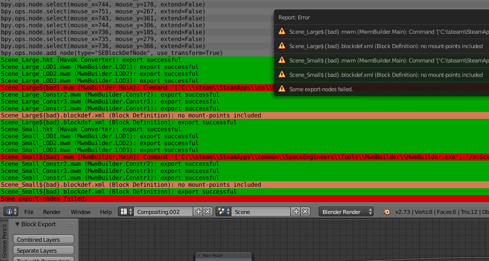
The add-on logs the result of each step of the export in Blender’s
info-log .
In addition the output of external tools is logged to separate log files that are named like the file that is
exported by the step with .log appended.
If an external tool fails for any reason or does not produce the expected file you should consult these log-files.
|
Block Definitions
When you export .mwm files the add-on also creates a corresponding .blockdef.xml file for each exported block.
This file contains all the information that is available in Blender and that is relevant
for a block’s <Definition> inside your mod’s CubeBlocks.sbc:
<Definition>
  <Id>
    <SubtypeId>ExampleBlock_Large</SubtypeId>
  </Id>
  <Icon>Textures\Icons\ExampleBlock.dds</Icon>
  <CubeSize>Large</CubeSize>
  <BlockTopology>TriangleMesh</BlockTopology>
  <Size x="1" y="1" z="1"/>
  <ModelOffset x="0" y="0" z="0"/>
  <Model>Models\ExampleBlock_Large.mwm</Model>
  <BuildProgressModels>
    <Model BuildPercentUpperBound="0.33" File="Models\ExampleBlock_Large_Constr1.mwm"/>
    <Model BuildPercentUpperBound="0.67" File="Models\ExampleBlock_Large_Constr2.mwm"/>
    <Model BuildPercentUpperBound="1.00" File="Models\ExampleBlock_Large_Constr3.mwm"/>
  </BuildProgressModels>
  <MountPoints>
    <MountPoint Side="Left" StartX="0.30" StartY="0.00" EndX="1.00" EndY="0.40"/>
    <MountPoint Side="Left" StartX="0.00" StartY="0.00" EndX="0.30" EndY="0.10"/>
    ...
  </MountPoints>
  <MirroringX>HalfY</MirroringX>
  <BlockPairName>ExampleBlock</BlockPairName>
</Definition>
This definition is incomplete. It only contains the parts Blender knows about.
You have to add missing properties like <TypeId> or <Components> yourself.
|
Updating CubeBlocks.sbc
You can use the "Update block definitions" operation to tell the add-on to take the same XML data
it writes to a .blockdef.xml file and merge it with matching <Definition> sections of your mod’s CubeBlocks.sbc.
That saves you the trouble to do this by hand.
Updating CubeBlocks.sbc will only work for blocks that are already present in the file.
The add-on searches for them by their <SubtypeId>.
|
Customizing the Export
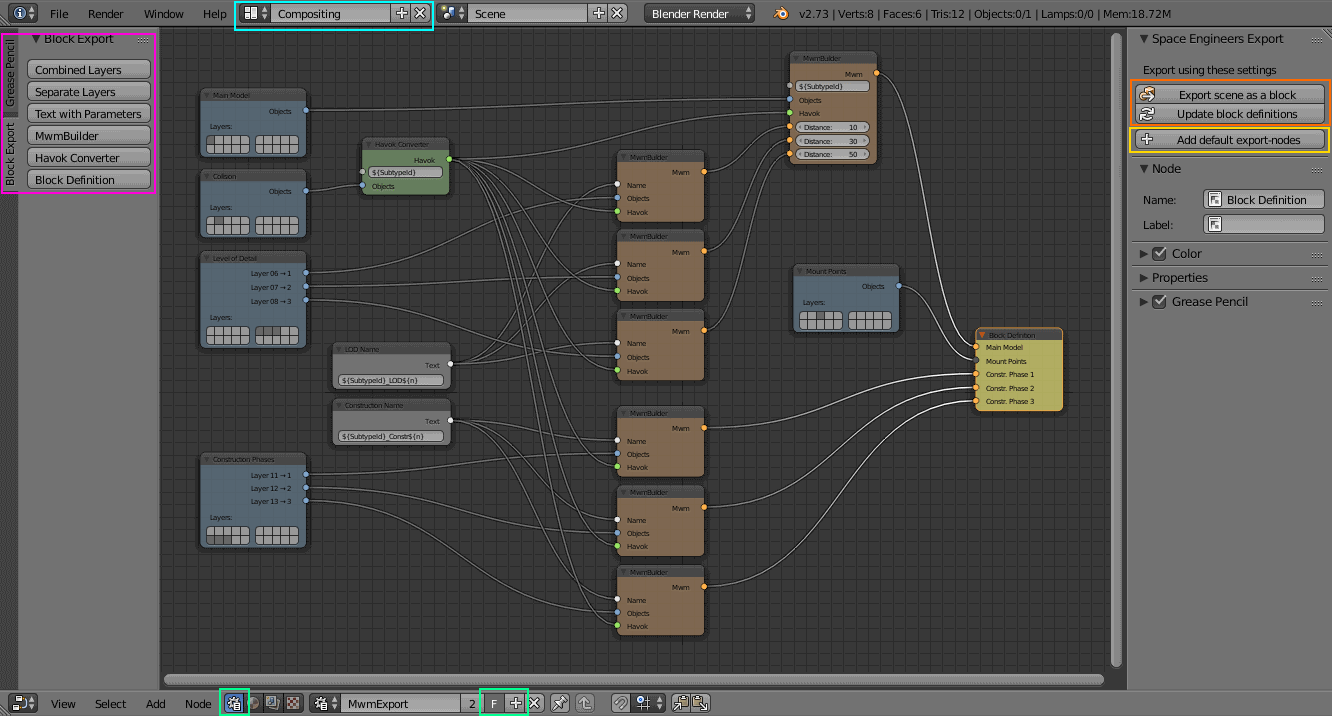
The add-on uses a custom Blender node-tree to drive the export. The connections between the nodes of that tree describe how the objects in the scene flow through the export.
The sockets of the nodes are color-coded to quickly recognized which sockets can connect to each other. The color-coding also signals if the connection between two nodes is dysfunctional by turning the sockets dark-grey. This happens if the nodes detect that no objects would flow between them — most probably because there are no objects. If an illegal connection is detected the affected sockets will be colored bright red.
Text Nodes and Sockets
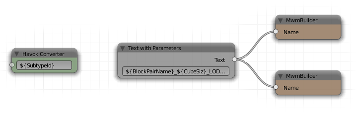
Several of the other nodes require text-input to name the files they produce. You can provide that text either directly via the corresponding white input-socket of each node or, if you want to reuse a text snippet, you can instead use a text-node and connect that to the input-socket. To avoid having to define an export node-tree for each scene all text-fields can use parameters that get substituted with information stored in the scene:
| Parameter Name | Description |
|---|---|
|
Contains the name of the scene. The suffixes |
|
Normally derived from the scene-name and the cube-size but can be explicitly configured in the scene properties. |
|
Either |
|
The sequence-number of the source-socket. See the next section for details. |
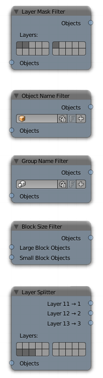
Object Filters
This kind of node determines the objects that should get processed. There are several variants. They all have an object-input socket so that you can build filter chains with them. If that input socket is not connected to anything it will use all objects in the scene as input.
Layer Mask Filter
This node uses a layer mask to filter out objects that are not on the marked layers.
Object Name Filter
This filter matches objects by their name. You can either choose an exact name or switch the node to use a regular expression. You can also invert the match so only objects get included that do not match the pattern.
Group Name Filter
This filter works just like an Object Name filter, only on the names of groups the object is in.
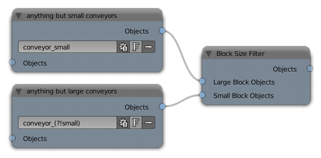
Block Size Filter
This node has two input sockets and selects between them depending on the currently exported block-size. This is useful if you have objects in your scene that should only be exported for one block-size but not for the other:
Layer Splitter
This node adds one output-socket for every layer you select.
Each of those sockets only provides the objects from the corresponding layer.
This is useful for sequential groups of meshes like construction stages.
The node also implicitly numbers the output-sockets starting at 1.
The number is available for text-substitution as parameter ${n}.
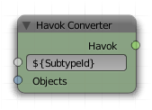
Havok Converter
This kind of node produces a .hkt file by taking the objects from its input-socket and running them first through
Blender’s FBX exporter, then through Havok’s FBX Importer and after that through Havok’s Standalone Filter Manager.
The node ignores objects that don’t have Rigid Body enabled on their Physics property-tab.
|
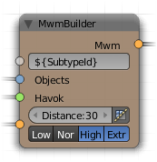
MwmBuilder
This kind of node produces a .mwm file by taking the objects from its input-socket and running
them through MwmBuilder. The node uses Blender’s FBX exporter internally.
The settings for the exporter are only available in the properties section of the node-tree’s N side-panel.
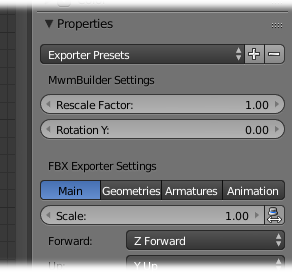
The default settings can be used as-is to export a block to SE. If you change the settings, you can save them as a preset. There already are presets to do character and animation exports and also to restore the default block settings.
The node will also include the collision data of a Havok Converter node if it is connected to one.
And lastly a MwmBuilder node can receive the output of other MwmBuilder nodes.
Those nodes will then serve as the level-of-detail models and the produced .mwm
will contain references to them.
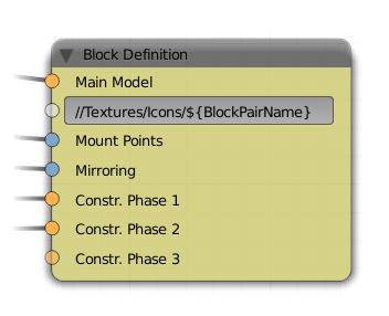
Block Definition
An export-tree can only contain a single node of this kind. The node takes the output from several other nodes to generate the block-definition for the scene. Of special note are the input-sockets for mount-points and mirroring-settings which are not consumed anywhere else in the export-tree.
| Updating CubeBlocks.sbc will be disabled if the export-tree contains no node of this kind. |